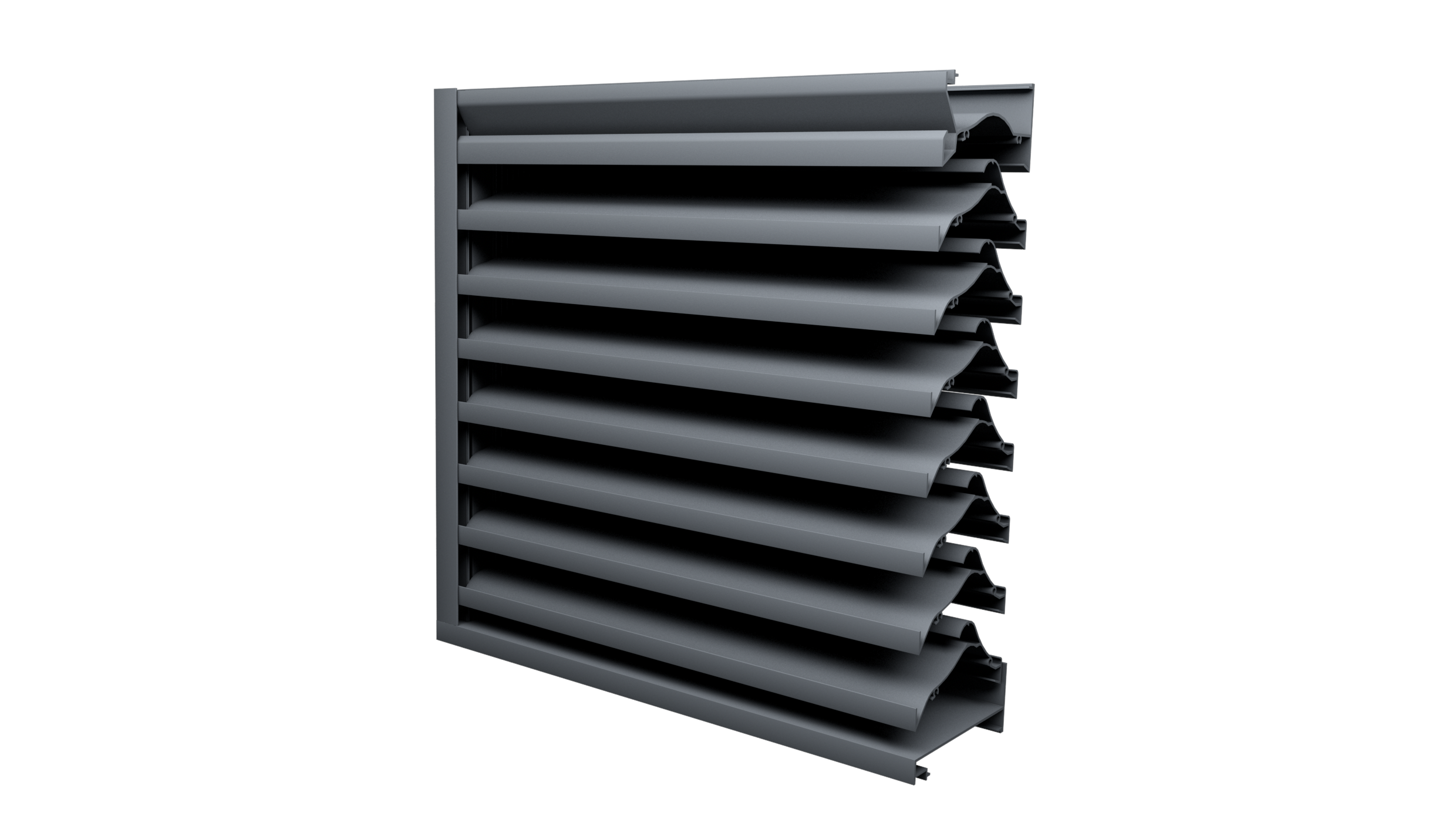
 Louvre pressure drop is one of the key parameters of establishing the louvre requirements for your project as it’s based on the needs of the building and its ventilation system, rather than “free area” which doesn’t really mean anything.
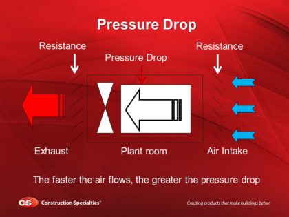
Pressure drop is defined as the pressure differential from one side of a louvre to the opposite side, often expressed in Pascals (Pa). Louvre pressure drop occurs when frictional forces, caused by the resistance to flow, act on air moving through a louvre.
Increased louvre pressure drop can prevent equipment inside the ventilated area drawing sufficient air through the louvre, resulting in overheating, as the equipment has to work harder to draw the air through.
For a real life example, think about what happens when you partially block the intake of a hairdryer. The increased pressure drop requires the motor to work harder to draw air through, reducing the amount of air getting through and the element overheats.
Scale this up to a real situation and consider air being drawn into a heating and ventilating system. The results could be catastrophic!
The Louvre Pressure Drop Calculation
There’s a formula you can use (pictured below), just plug in the numbers in the right places and you (should) have the right answer. This pressure drop number must be passed to your mechanical engineer for them to determine whether this number is acceptable. If it isn’t you may need to consider increasing, or decreasing, the amount of louvre on your building.
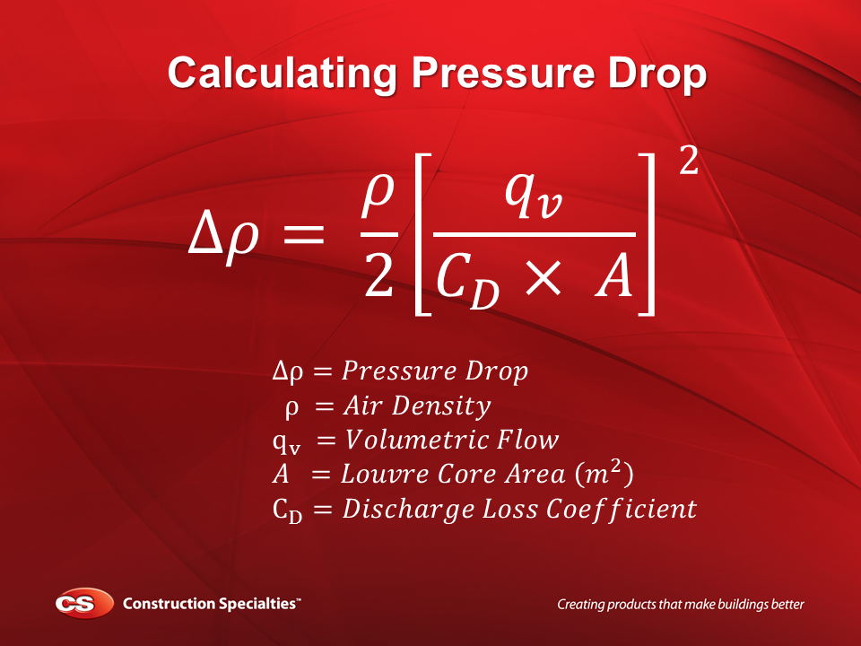
Air Density (ρ)
is generally 1.225 kg/m³ (at sea level)
Volumetric Flow (qv)
is supplied by the ventilation engineer and relates to the amount of air required through the system
Core Area (A) & Discharge Loss Coefficient (CD)
are provided by your chosen louvre manufacturer
Example Louvre Pressure Drop Calculation
For this example we are working from an example structural opening of 2m² and have decided to specify the CS RSH-5700 Performance Louvre which has a coefficient of 0.32. The Core area, the area of the louvre without mullions, jamb and head, would be 1.796m². Our mechanical engineer has told us that he requires a Volumetric Flow of 3.78m³ for his air conditioning unit to operate efficiently, and we have assumed an air density of 1.225 kg/m³.
Opening

Overall opening = 2m²
Core Area
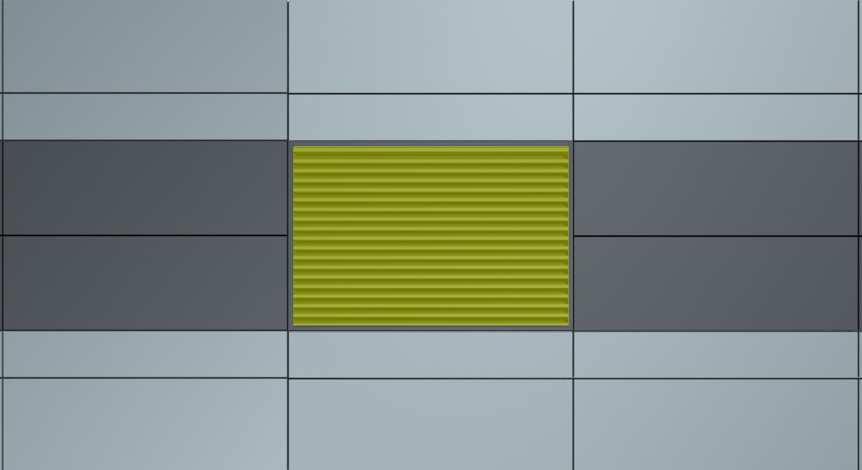
Core Area = 1.796m²
Volumetric Flow

Volumetric Flow = 3.78m³
Now that we have established that information we can start plugging it into the formula we mentioned above.
To make sure you get an accurate result we’ve actually created an Pressure Drop Calculator to work everything out for you, which you can use below:
Guidance
Air Density (ρ)
is generally 1.225 kg/m³ (at sea level)
Volumetric Flow (qv)
is supplied by the ventilation engineer and relates to the amount of air required through the system
Core Area (A)
The minimum height times the minimum width of the front opening in a louvre assembly with the louvre blades removed.
There is also an Excel version of the above tool which you can download too:
Or alternatively, using your trusty calculator, you can follow the instructions below to work everything out manually.
1 - Starting Formula

2 - Input Figures
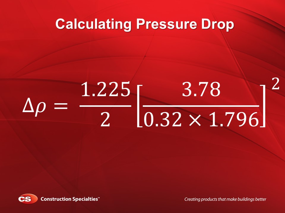
3 - Multiply Discharge Loss & Area
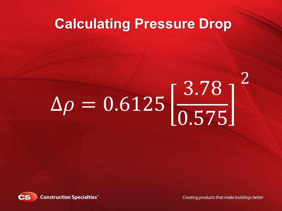
4 - Divide Volumetric Flow
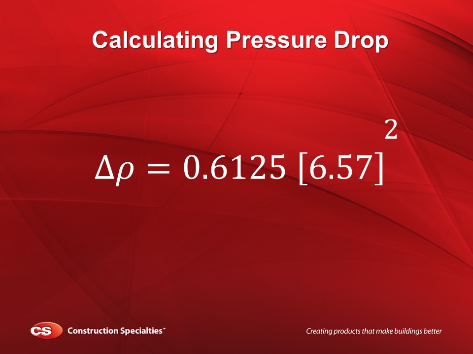
5. Multiply Remaining Figures
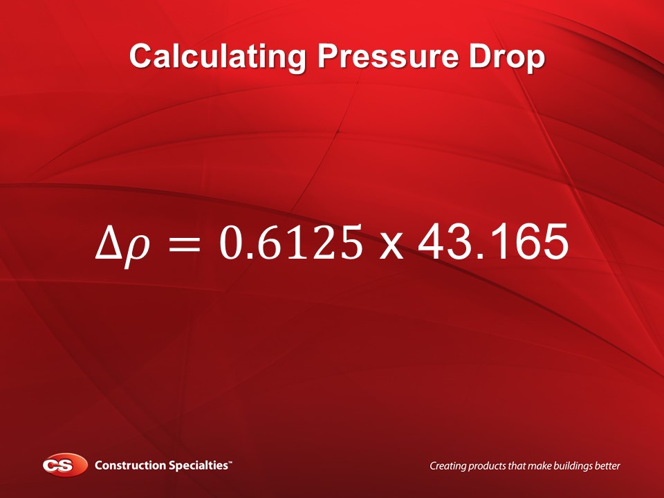
6 - Pressure Drop Result
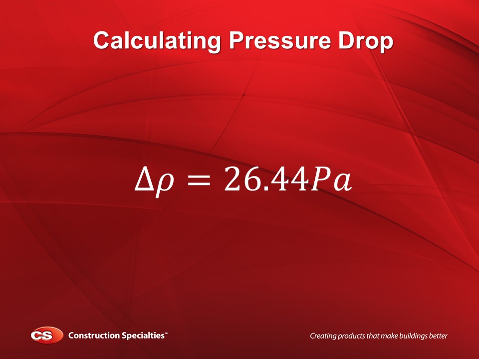
So there you have it, that’s how you calculate Louvre pressure drop, if you get stuck, confused or need any help please let us know, we’re happy to help. We’ve got a lot of experience in louvre specification so feel free to get in touch.

Need more help? Download our FREE Guide to Specifying Architectural Louvres
Learn how to correctly specify Architectural Louvres for your project
